Transducer Interface
Remote Transducer Interface (RT Variants Only)
Overview
The C-Series Modem Remote Transducer Interface applies only to RT variants: C1500RP-55-RT-00 and C3500RP-55-RT-00. Non-RT C-Series variants, including C1500LI-00 and C1500RP-55-00, do not have this external remote-transducer connector.
The interface consists of a single wet-mate bulkhead connector available to connect the transducer to the modem.
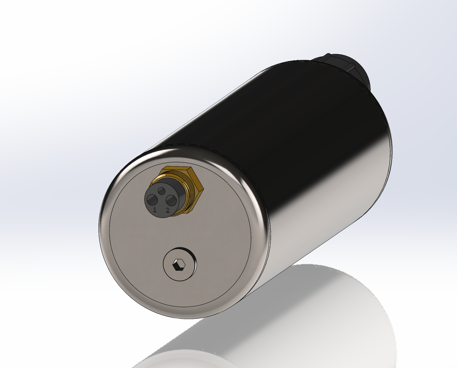
Electrical Connections
| Pin Number | I/O | Pin Name | Notes |
|---|---|---|---|
1 | IO | SIGNAL | Transducer positive lead |
2 | P | GND | Board ground |
Hardware Components
The C1500RP Remote Transducer Interface connector is a MacArtney SubConn Micro Circular 2-pin female aluminum bulkhead connector, P/N MCBH2FAS, with integral male locking sleeve threads.
The C3500RP Remote Transducer Interface connector is a MacArtney SubConn Micro Circular 2-pin female titanium bulkhead connector, P/N MCBH2FTI, with integral male locking sleeve threads.
The Remote Transducer Interface is connected using a SubConn Micro Circular 2-pin male inline cable, P/N MCIL2M, and female locking sleeve, P/N MCDLS-F BLUE, or a pre-terminated transducer such as PMT-28-2M-MCM-00 or PMT-10-1M-MCM-00.
The pinout diagram below is for the external mating connector, male pins, not the modem connector, female pins.

Mating Cable Notes
Connectors must be greased with MOLYKOTE 44 Medium before every mating.
- Disconnect by pulling straight out, not at an angle.
- Do not pull on the cable and avoid sharp bends at cable entry.
- Ensure that there are no angular loads on the bulkhead connector.
- SubConn connectors should not be exposed to extended periods of heat or direct sunlight. If a connector becomes very dry, soak it in fresh water before use.
- The locking sleeve must be hand-tightened only.
- Color codes may differ for unterminated inline cables depending on vendor. Refer to the connector pinout above for pin and signal locations, and verify with a digital multimeter before terminating.