Power & Communication Interface
Overview
The M-Series Modem Power & Communication Interface consists of a single wet-mate bulkhead connector available to provide power and communicate via Ethernet at 10/100 Mbps, RS-232, and/or RS-422 full-duplex.
Electrical Connections
The figure below shows the electrical connections for the Power & Communication Interface. All signal directions are relative to the M-Series Modem.
This is the face view of the male connector as mated to M-Series. M-Series has a female connector, and the pinout will appear mirror-imaged on the modem unit.
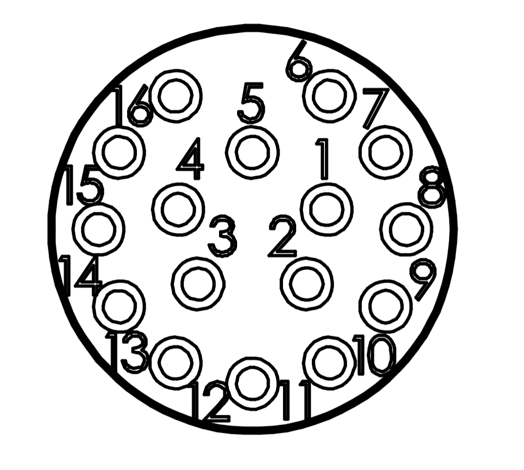
| Pin Number | I/O | Pin Name | Notes |
|---|---|---|---|
1 | P | LED Power | +3.3 V out when unit is powered up |
2 | O | RS-422 TX+ | RS-422 transmit positive |
3 | O | RS-422 TX- | RS-422 transmit negative |
4 | I | RS-422 RX+ | RS-422 receive positive |
5 | I | RS-422 RX- | RS-422 receive negative |
6 | I | Power Switch | Short to GND to power down unit. Leave open for normal operation. |
7 | P | GND | Communication interfaces GND, electrically connected to pin 15 |
8 | O | ENET_DP0_P | T568A: green & white T568B: orange & white |
9 | O | ENET_DP0_N | T568A: green T568B: orange |
10 | I | ENET_DP1_P | T568A: orange & white T568B: green & white |
11 | I | ENET_DP1_N | T568A: orange T568B: green |
12 | O | RS-232 TX | RS-232 transmit |
13 | I | RS-232 RX | RS-232 receive |
14 | I | 1PPS Input | Used for 1PPS or general-purpose digital input. +1.8 V to +5 V logic level. |
15 | P | GND | Power input ground, electrically connected to pin 7 |
16 | P | VIN | Charger input, LIC-77WH-00: 25.5 V |
Connector Hardware Components
The M-Series Power & Communication Interface connector is a MacArtney SubConn Micro Circular 16-pin female aluminum (M2000) or titanium (M6000) bulkhead connector, P/N MCBH16FAS or MCBH16FTI, and female locking sleeve, P/N DLSA-F BLUE.
The Power & Communication Interface is connected using a MacArtney SubConn Micro Circular 16-pin male inline cable, P/N MCIL16M, and male locking sleeve, P/N DLSA-M BLUE. The M-Series comes with a power-down plug mounted, which keeps pins 6 and 7 shorted and the modem powered down. The install kit for M-Series also includes an inline cable adapter, Popoto PDI board, battery charger, and dummy plug for easy interfacing with the modem.
Mating Cable Notes
Connectors must be greased with MOLYKOTE 44 Medium before every mating.
- Disconnect by pulling straight out, not at an angle.
- Do not pull on the cable and avoid sharp bends at cable entry.
- Ensure that there are no angular loads on the bulkhead connector.
- SubConn connectors should not be exposed to extended periods of heat or direct sunlight. If a connector becomes very dry, soak it in fresh water before use.
- The locking sleeve must be hand-tightened only.
- If using RS-422, mating cables should use twisted-pair wiring for pins
2/3and4/5. - If using Ethernet, mating cables should use twisted-pair wiring, ideally
100 ohmdifferential impedance, for pins8/9and10/11. - If using alternate vendors for cabling, the color code may differ. Refer to the connector pinout above for pin and signal locations, and verify with a digital multimeter before terminating.
| Pin Number | Wire Color |
|---|---|
1 | Red |
2 | Red/White |
3 | Black |
4 | Black/White |
5 | Yellow |
6 | Yellow/White |
7 | Blue |
8 | Blue/White |
9 | Orange |
10 | Orange/White |
11 | Brown |
12 | Brown/White |
13 | Grey |
14 | Grey/White |
15 | Green |
16 | Green/White |
| Pin Number | Wire Color |
|---|---|
1 | Black |
2 | White |
3 | Red |
4 | Green |
5 | Orange |
6 | Blue |
7 | White/Black |
8 | Red/Black |
9 | Green/Black |
10 | Orange/Black |
11 | Blue/Black |
12 | Black/White |
13 | Red/White |
14 | Green/White |
15 | Blue/White |
16 | Black/Red |