Auxiliary and Analog Interfaces
RTC Coin Cell Interface
Overview
The RTC Coin Cell Interface provides coin-cell backup power to the OEM modem's real-time clock, allowing calendar time to be retained across main-battery power cycles.
Electrical Connections
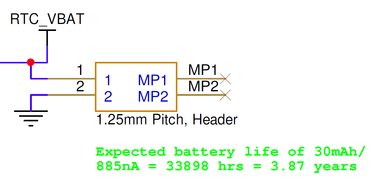
All signal directions are relative to the OEM modem. Refer to the digital board connector locations figure for the connector's physical location.
| Pin Number | I/O | Pin Name | Notes |
|---|---|---|---|
1 | P | RTC_VBAT | RTC battery backup voltage supply, 1.0–5.0 V, nominal 3.0 V |
2 | P | GND | Board ground |
Hardware Components
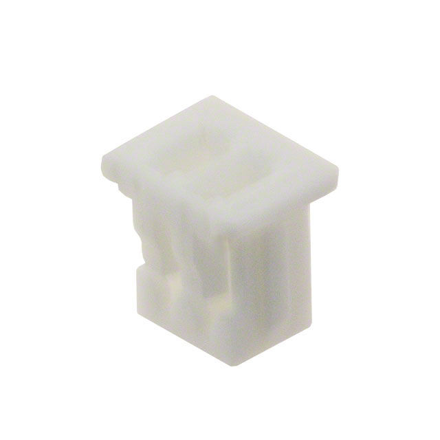
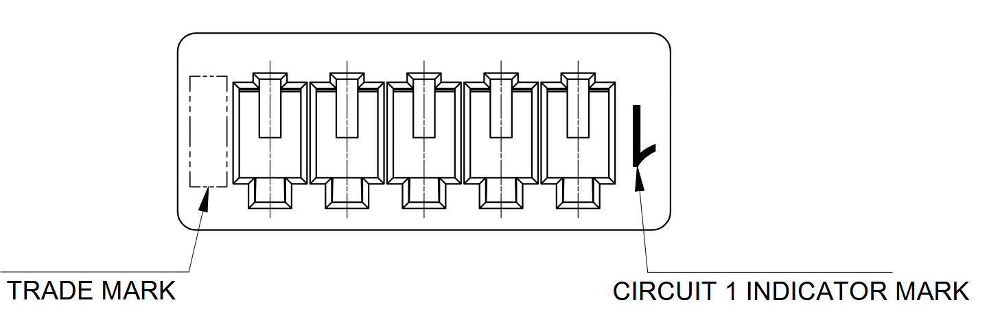
The RTC Coin Cell Interface uses a Molex PicoBlade connector, P/N 0510210200, or equivalent. The recommended contacts are Molex P/N 0500798000, suitable for 26–28 AWG wire.
| Part Number | Manufacturer | Description |
|---|---|---|
0510210200 | Molex | PicoBlade 2-position connector receptacle, 1.25 mm pitch |
0500798000 | Molex | PicoBlade 26–28 AWG sockets |
2002181900 | Molex | PicoBlade hand crimp tool |
2149202211 | Molex | Pre-crimped PicoBlade lead, 75 mm length |
Hydrophone Input Interface
Overview
The two Hydrophone Input Interface connectors digitize acoustic data from up to eight hydrophones in addition to the standard acoustic transducer interface.
Electrical Connections
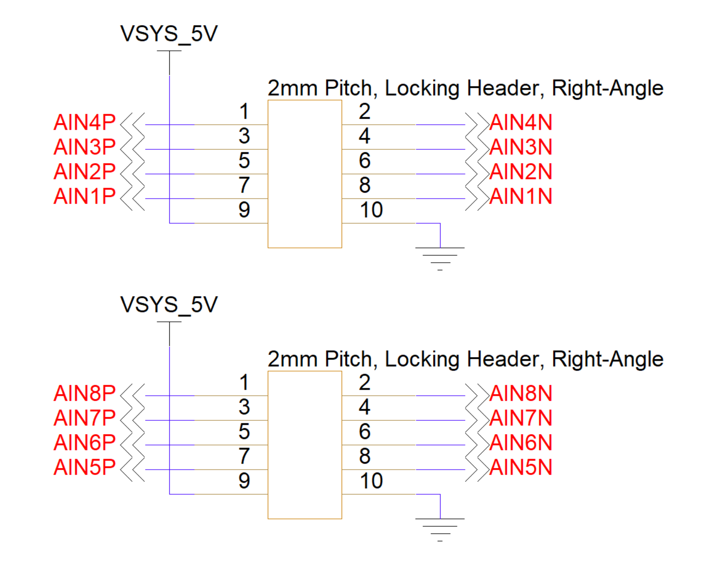
Each hydrophone input is single-ended; the AINxN returns are tied internally to board ground. Each input is AC-coupled through a 10,000 pF capacitor with a 158 kΩ resistor, producing a 100 Hz high-pass cutoff and approximately 158 kΩ pass-band input impedance.
On PMM6081 units manufactured before mid-2026, odd-numbered inputs (AIN1, AIN3, AIN5, and AIN7) default to 43 dB gain and even-numbered inputs default to 12 dB. On units manufactured after mid-2026, all hydrophone inputs default to 43 dB gain.
The full-scale ADC input is 5.32 V peak-to-peak. This corresponds to 37.3 mV peak-to-peak at a 43 dB input and 1.34 V peak-to-peak at a 12 dB input. Contact info@popotomodem.com for other gain configurations.
Refer to the digital board connector locations figure for the connectors' physical locations.
| Pin Number | I/O | Pin Name | Notes |
|---|---|---|---|
1 | I | AIN4P | Hydrophone input |
2 | P | AIN4N | Hydrophone return |
3 | I | AIN3P | Hydrophone input |
4 | P | AIN3N | Hydrophone return |
5 | I | AIN2P | Hydrophone input |
6 | P | AIN2N | Hydrophone return |
7 | I | AIN1P | Hydrophone input |
8 | P | AIN1N | Hydrophone return |
9 | P | VSYS_5V | +5 V out when unit is powered up |
10 | P | GND | Board ground |
| Pin Number | I/O | Pin Name | Notes |
|---|---|---|---|
1 | I | AIN8P | Hydrophone input |
2 | P | AIN8N | Hydrophone return |
3 | I | AIN7P | Hydrophone input |
4 | P | AIN7N | Hydrophone return |
5 | I | AIN6P | Hydrophone input |
6 | P | AIN6N | Hydrophone return |
7 | I | AIN5P | Hydrophone input |
8 | P | AIN5N | Hydrophone return |
9 | P | VSYS_5V | +5 V out when unit is powered up |
10 | P | GND | Board ground |
Hardware Components
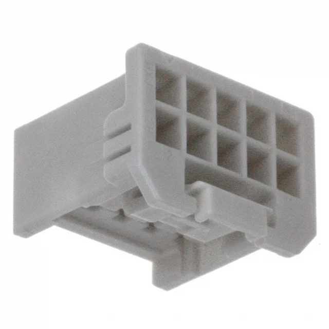
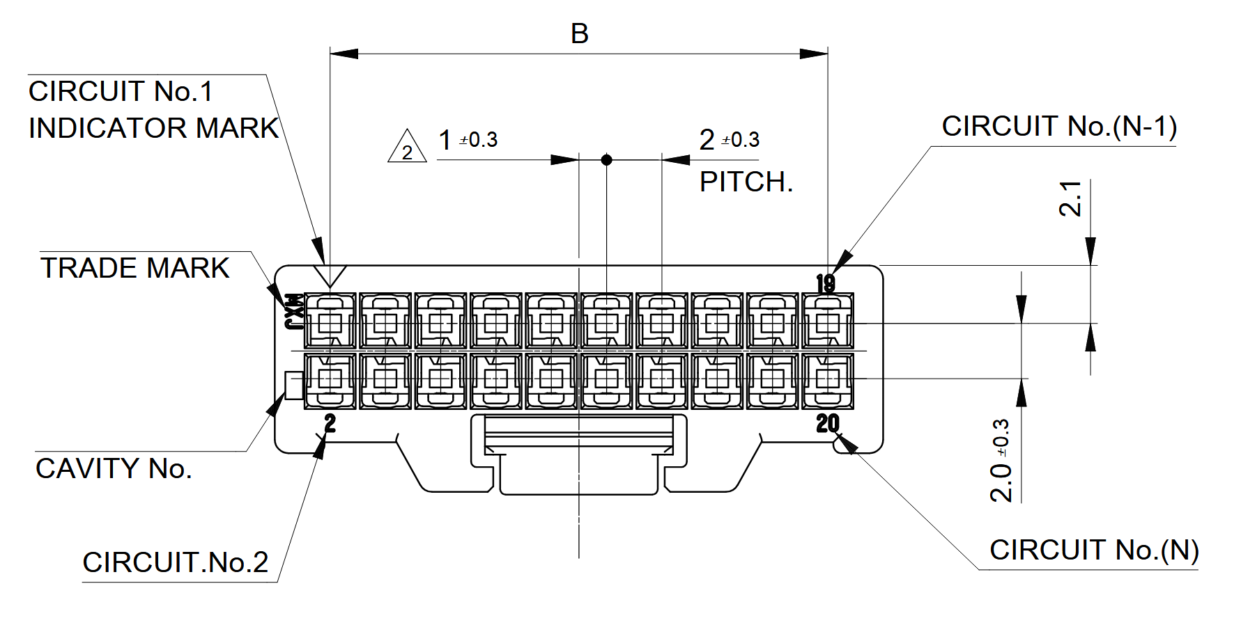
Each Hydrophone Input Interface uses a Molex iGrid connector, P/N 5016461000, or equivalent. The recommended contacts are Molex P/N 5016471000, suitable for 22–26 AWG wire. They can be crimped with Molex hand tool 0638192300; pre-crimped leads may also be used.
| Part Number | Manufacturer | Description |
|---|---|---|
5016461000 | Molex | iGrid 10-position connector receptacle, 2.0 mm pitch |
5016471000 | Molex | iGrid 22–26 AWG sockets |
0638192300 | Molex | iGrid 22–26 AWG hand crimp tool |
2174912225 | Molex | Pre-crimped iGrid 22 AWG lead, 450 mm length |
Mating Cable Notes
- Route all hydrophone connections carefully to minimize noise pickup.
- Attach or detach the interface only while power is disconnected from the OEM modem to avoid electrical damage.
Analog Line Input Interface
Overview
The Analog Line Input Interface accepts an analog signal into the receiver pathway. The transducer receiver is normally digitized at separate 43 dB and 12 dB gains; using analog line input disconnects the transducer from the 12 dB pathway.
Move the Analog Input Selection Jumper from pins 1/2 to pins 2/3 before using this interface.
Electrical Connections
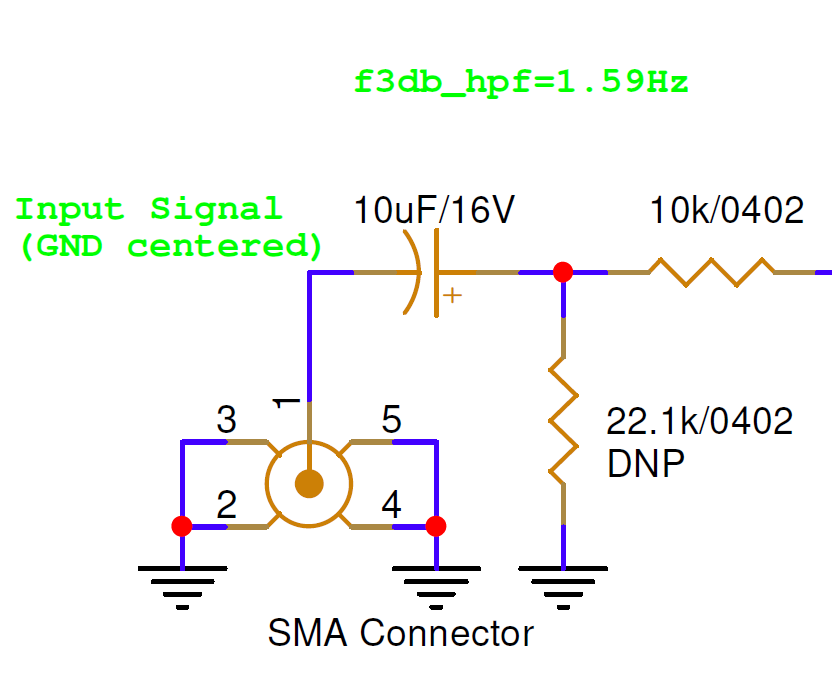
The interface is single-ended and AC-coupled through a 10 µF capacitor with a 10 kΩ input resistor, producing a 1.59 Hz high-pass cutoff and approximately 10 kΩ pass-band input impedance. Gain is −1 V/V with an intentional 123 kHz low-pass roll-off. The full-scale ADC input is 5.32 V peak-to-peak.
| Pin Number | I/O | Pin Name | Notes |
|---|---|---|---|
1, SMA center | I | LINE_IN | Analog line input |
2–5, SMA shell | P | GND | Board ground |
Hardware Components
The Analog Line Input Interface accepts any standard SMA cable. One example is TE Connectivity P/N CSE-SGAM-305-SGAM.
Analog Line Output Interface
Overview
The Analog Line Output Interface provides an analog signal from the transmitter pathway.
Electrical Connections
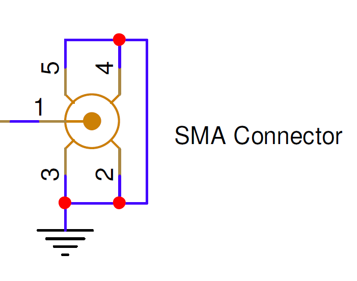
The transmitter pathway contains a two-channel stereo DAC. The left channel drives the Transducer Interface and the right channel drives the Analog Line Output Interface. The line output is single-ended and DC-coupled, with a minimum supported load of 32 Ω and a full-scale output of 1.58 V RMS.
| Pin Number | I/O | Pin Name | Notes |
|---|---|---|---|
1, SMA center | O | LINE_OUT | Analog line output |
2–5, SMA shell | P | GND | Board ground |
Hardware Components
The Analog Line Output Interface accepts any standard SMA cable. One example is TE Connectivity P/N CSE-SGAM-305-SGAM.