Popoto Digital Interface
Overview
The Popoto Digital Interface (PDI) is a single connector that provides power, 10/100 Mbps Ethernet, full-duplex RS-232 or RS-422 communication, power control, and a 1PPS time-sync input.
Electrical Connections
All signal directions are relative to the OEM modem. Refer to the digital board connector locations figure for the connector's physical location.
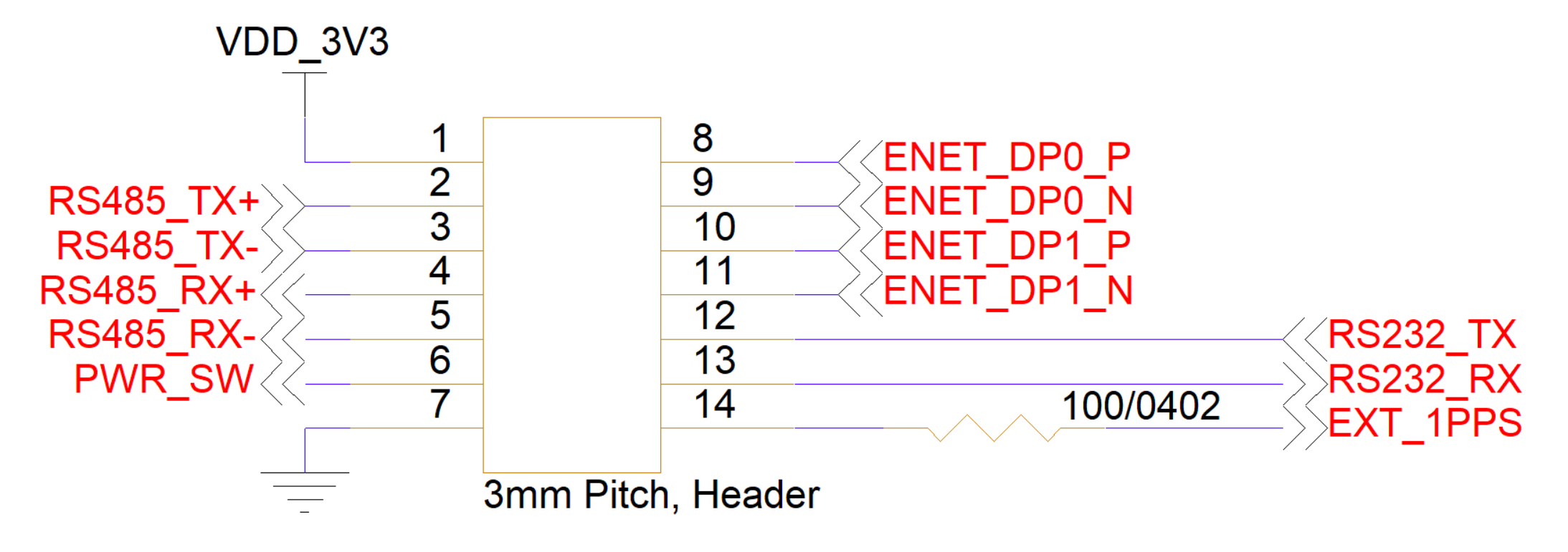
| Pin Number | I/O | Pin Name | Notes |
|---|---|---|---|
1 | P | VDD_3V3 | +3.3 V out when unit is powered up |
2 | O | RS-422 TX+ | RS-422 transmit positive |
3 | O | RS-422 TX- | RS-422 transmit negative |
4 | I | RS-422 RX+ | RS-422 receive positive |
5 | I | RS-422 RX- | RS-422 receive negative |
6 | I | Power Switch | Short to GND to power down the unit; leave open for normal operation |
7 | P | GND | Board ground |
8 | O | ENET_DP0_P | T568A: green/white T568B: orange/white |
9 | O | ENET_DP0_N | T568A: green T568B: orange |
10 | I | ENET_DP1_P | T568A: orange/white T568B: green/white |
11 | I | ENET_DP1_N | T568A: orange T568B: green |
12 | O | RS-232 TX | RS-232 transmit |
13 | I | RS-232 RX | RS-232 receive |
14 | I | 1PPS Input | 1PPS or general-purpose digital input, +1.8 V to +5 V logic level |
Hardware Components
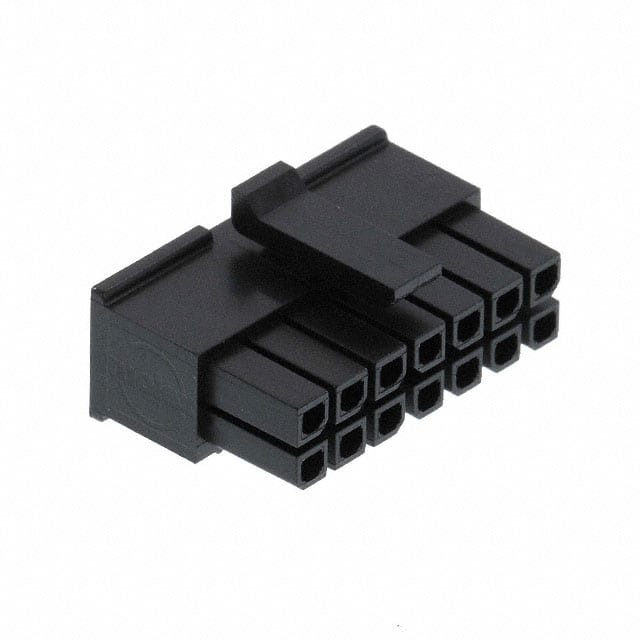
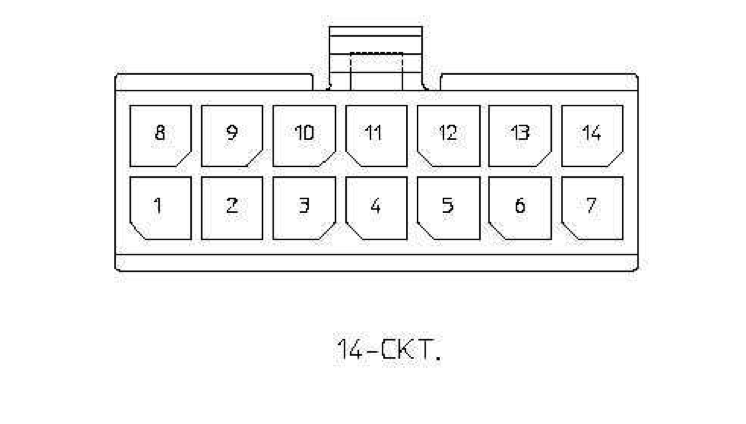
The PDI uses a Molex Micro-Fit 3.0 connector, P/N 0430251400, or equivalent. The recommended contacts are Molex P/N 0462355001. These gold-plated, low-insertion-force contacts are rated for 250 mating cycles and are suitable for 20–24 AWG wire. They can be crimped with Molex hand tool 0638190000; pre-crimped leads may also be used.
| Part Number | Manufacturer | Description |
|---|---|---|
0430251400 | Molex | Micro-Fit 3.0 14-position connector receptacle, 3.0 mm pitch |
0462355001 | Molex | Micro-Fit 3.0 20–24 AWG gold-plated, lubricated sockets |
0638190000 | Molex | Micro-Fit 3.0 hand crimp tool |
2147611215 | Molex | Pre-crimped Micro-Fit 3.0 lead, 450 mm length |
Mating Cable Notes
- RS-422 mating cables must use twisted-pair wiring for pins
2/3and4/5. - Ethernet mating cables must use twisted-pair wiring, ideally with 100-ohm differential impedance, for pins
8/9and10/11. - Attach or detach the interface only while power is disconnected from the OEM modem to avoid electrical damage.