Gigabit Ethernet Expansion Interface
Overview
The Gigabit Ethernet Expansion Interface provides the third and fourth differential pairs required to enable Gigabit Ethernet on the OEM modem. It is used together with the two Ethernet pairs on the PDI.
Electrical Connections
All signal directions are relative to the OEM modem. Refer to the digital board connector locations figure for the connector's physical location.
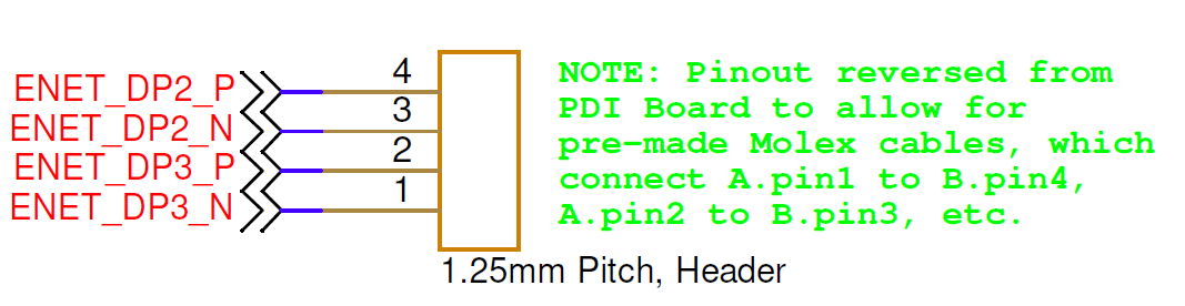
| Pin Number | I/O | Pin Name | Notes |
|---|---|---|---|
4 | I/O | ENET_DP2_P | T568A/T568B: blue |
3 | I/O | ENET_DP2_N | T568A/T568B: blue/white |
2 | I/O | ENET_DP3_P | T568A/T568B: brown/white |
1 | I/O | ENET_DP3_N | T568A/T568B: brown |
Hardware Components
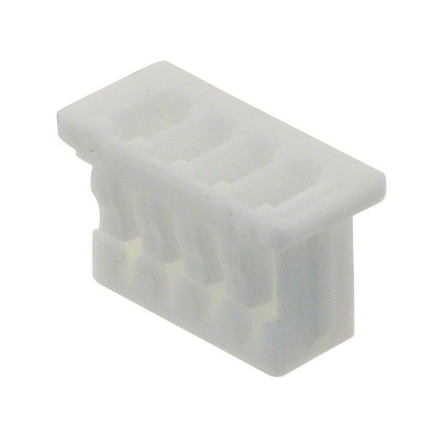
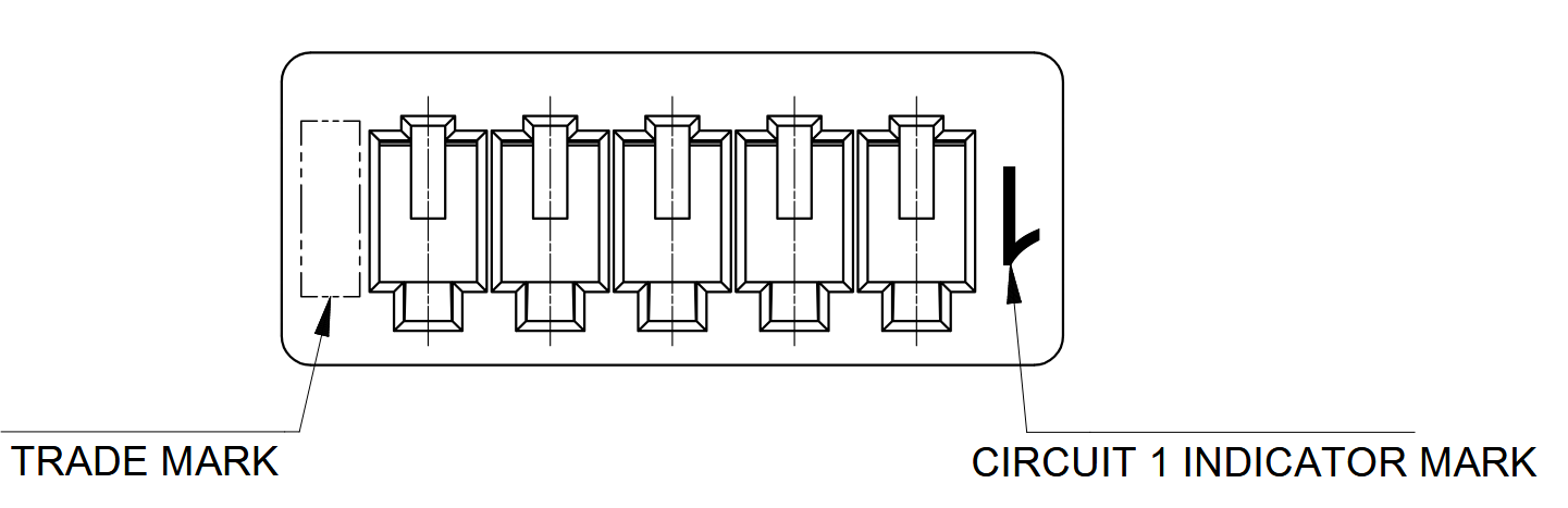
The Gigabit Ethernet Expansion Interface uses a Molex PicoBlade connector, P/N 0510210400, or equivalent. The recommended contacts are Molex P/N 0500798000, suitable for 26–28 AWG wire. They can be crimped with Molex hand tool 2002181900; pre-crimped leads may also be used.
| Part Number | Manufacturer | Description |
|---|---|---|
0510210400 | Molex | PicoBlade 4-position connector receptacle, 1.25 mm pitch |
0500798000 | Molex | PicoBlade 26–28 AWG sockets |
2002181900 | Molex | PicoBlade hand crimp tool |
2149202211 | Molex | Pre-crimped PicoBlade lead, 75 mm length |
Mating Cable Notes
- The pinout is reversed relative to the PDI board to support pre-made Molex cables that connect A.pin1 to B.pin4, A.pin2 to B.pin3, and so on.
- Use twisted-pair wiring, ideally with 100-ohm differential impedance, for pins
4/3and2/1. - Attach or detach the interface only while power is disconnected from the OEM modem to avoid electrical damage.