Control and Expansion Interfaces
MPU Expansion Interface
Overview
The MPU Expansion Interface communicates with the modem MPU using +5 V logic-level SPI, I2C, and GPIO peripherals. All pins on this expansion header are level-translated from the internal logic voltage to +5 V for robustness.
Electrical Connections
All signal directions are relative to the OEM modem. Refer to the digital board connector locations figure for the connector's physical location.
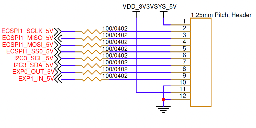
| Pin Number | I/O | Pin Name | Notes |
|---|---|---|---|
1 | P | VSYS_5V | +5 V out when unit is powered up |
2 | O | ECSPI1_SCLK_5V | SPI serial clock |
3 | I | ECSPI1_MISO_5V | SPI Master In Slave Out |
4 | O | ECSPI1_MOSI_5V | SPI Master Out Slave In |
5 | O | ECSPI1_SS0_5V | SPI slave select |
6 | O | I2C3_SCL_5V | I2C clock, maximum 400 kHz |
7 | I/O | I2C3_SDA_5V | I2C data |
8 | O | EXP0_OUT_5V | General-purpose digital output |
9 | I | EXP1_IN_5V | General-purpose digital input |
10 | P | GND | Board ground |
11 | P | VDD_3V3 | +3.3 V out when unit is powered up |
12 | P | GND | Board ground |
Because of the internal 5 V level translators, the signal directions shown above are fixed and cannot be modified.
Hardware Components
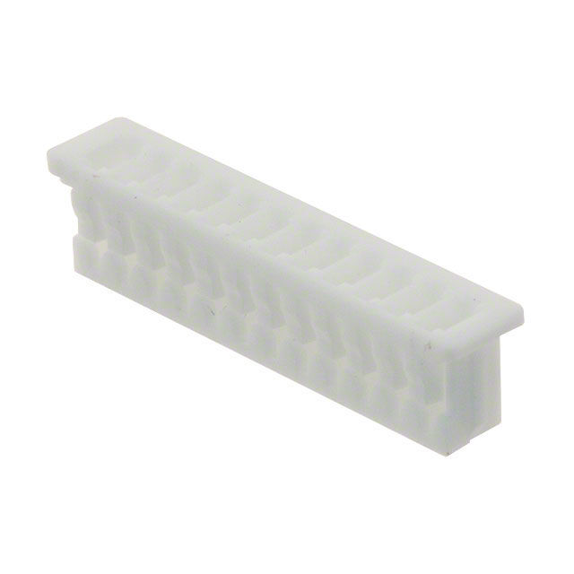
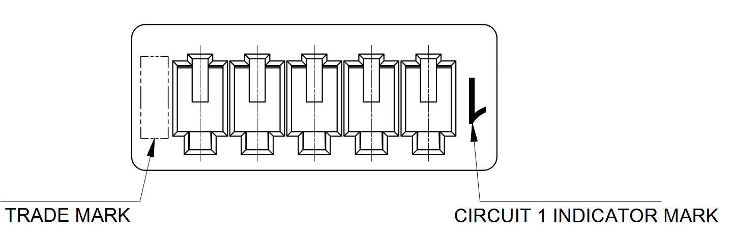
The MPU Expansion Interface uses a Molex PicoBlade connector, P/N 0510211200, or equivalent. The recommended contacts are Molex P/N 0500798000, suitable for 26–28 AWG wire. They can be crimped with Molex hand tool 2002181900; pre-crimped leads may also be used.
| Part Number | Manufacturer | Description |
|---|---|---|
0510211200 | Molex | PicoBlade 12-position connector receptacle, 1.25 mm pitch |
0500798000 | Molex | PicoBlade 26–28 AWG sockets |
2002181900 | Molex | PicoBlade hand crimp tool |
2149202211 | Molex | Pre-crimped PicoBlade lead, 75 mm length |
Mating Cable Notes
Attach or detach the interface only while power is disconnected from the OEM modem to avoid electrical damage.
Wakeup MCU Expansion Interface
Overview
The Wakeup MCU Expansion Interface communicates with the wakeup MCU using +1.8 V logic-level analog and digital peripherals.
This interface uses the same physical connector as the MPU Expansion Interface, but it does not use the same pinout. Contact info@popotomodem.com if your application requires this interface.
Analog Board Expansion Interface
Overview
The Analog Board Expansion Interface communicates with the modem MPU using +3.3 V logic-level digital peripherals. All pins are level-translated from the internal logic voltage to +3.3 V for robustness.
Electrical Connections
All signal directions are relative to the OEM modem. Refer to the analog board connector locations figure for the connector's physical location.
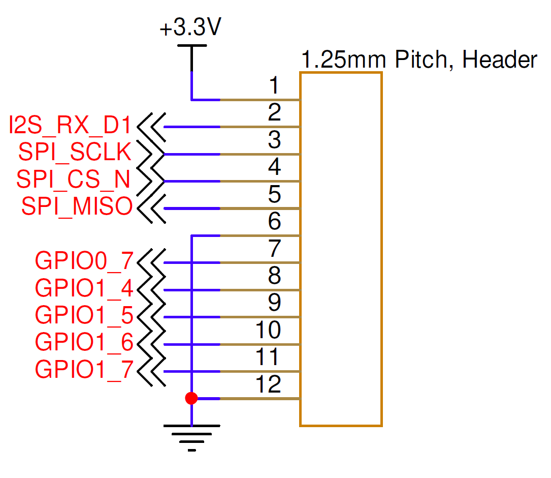
| Pin Number | I/O | Pin Name | Notes |
|---|---|---|---|
1 | P | +3.3V | +3.3 V out when unit is powered up |
2 | I | I2S_RX_D1 | I2S receive data pin |
3 | O | SPI_SCLK | SPI serial clock |
4 | O | SPI_CS_N | SPI slave select |
5 | I | SPI_MISO | SPI Master In Slave Out |
6 | P | GND | Board ground |
7 | I/O | GPIO0_7 | General-purpose I/O |
8 | I/O | GPIO1_4 | General-purpose I/O |
9 | I/O | GPIO1_5 | General-purpose I/O |
10 | I/O | GPIO1_6 | General-purpose I/O |
11 | I/O | GPIO1_7 | General-purpose I/O |
12 | P | GND | Board ground |
Contact info@popotomodem.com if your application requires the Analog Board Expansion Interface.
Hardware Components
The Analog Board Expansion Interface uses a Molex PicoBlade connector, P/N 0510211200, or equivalent. The recommended contacts are Molex P/N 0500798000, suitable for 26–28 AWG wire.
| Part Number | Manufacturer | Description |
|---|---|---|
0510211200 | Molex | PicoBlade 12-position connector receptacle, 1.25 mm pitch |
0500798000 | Molex | PicoBlade 26–28 AWG sockets |
2002181900 | Molex | PicoBlade hand crimp tool |
2149202211 | Molex | Pre-crimped PicoBlade lead, 75 mm length |
Mating Cable Notes
Attach or detach the interface only while power is disconnected from the OEM modem to avoid electrical damage.