Transducer Interface
Overview
The Transducer Interface attaches the acoustic communications transducer.
OEM modems manufactured before mid-2025 use a 6-pin connector. Newer units use a 3-pin terminal-block connector. Both versions are documented below; the analog board connector locations figure shows the newer 3-pin version.
3-Pin Interface — Mid-2025 and Later
All signal directions are relative to the OEM modem.
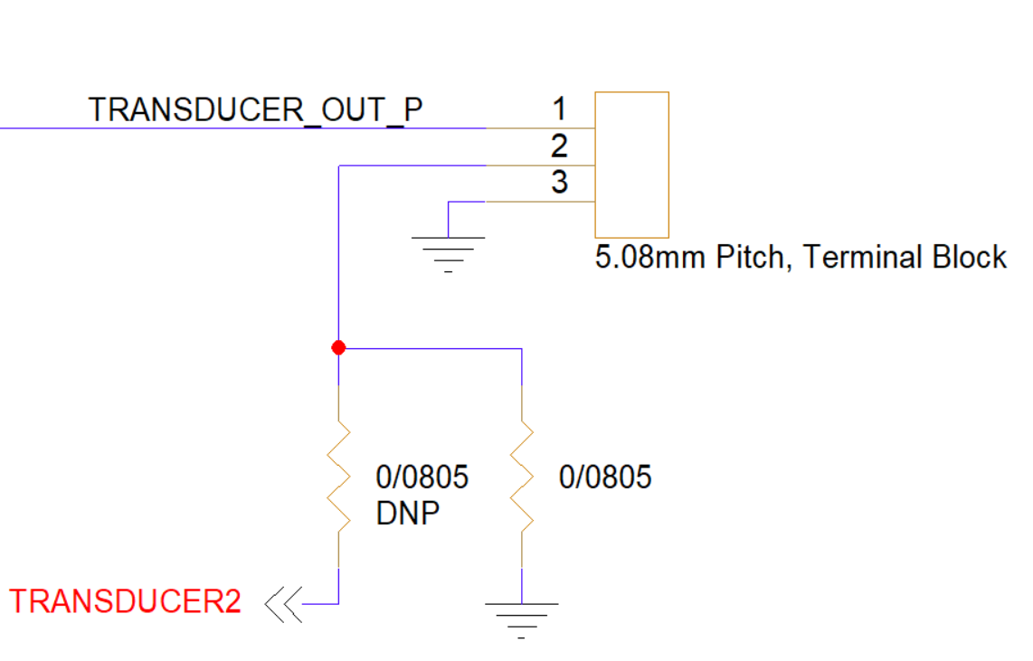
| Pin Number | I/O | Pin Name | Notes |
|---|---|---|---|
1 | O | TRANSDUCER_OUT_P | Transducer output |
2 | P/I | GND/TRANSDUCER2 | Board ground or second transducer input |
3 | P | GND | Board ground |
- Connect the transducer between pins
1and3, with the shield, if present, connected to pin2. - For a second receive-only transducer, contact info@popotomodem.com. By default, pin
2is identical to pin3and connected to board ground.
Hardware Components
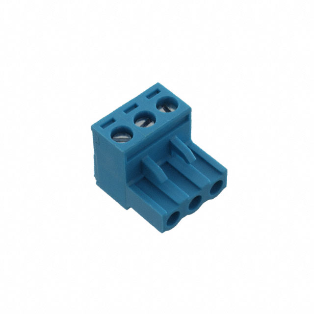
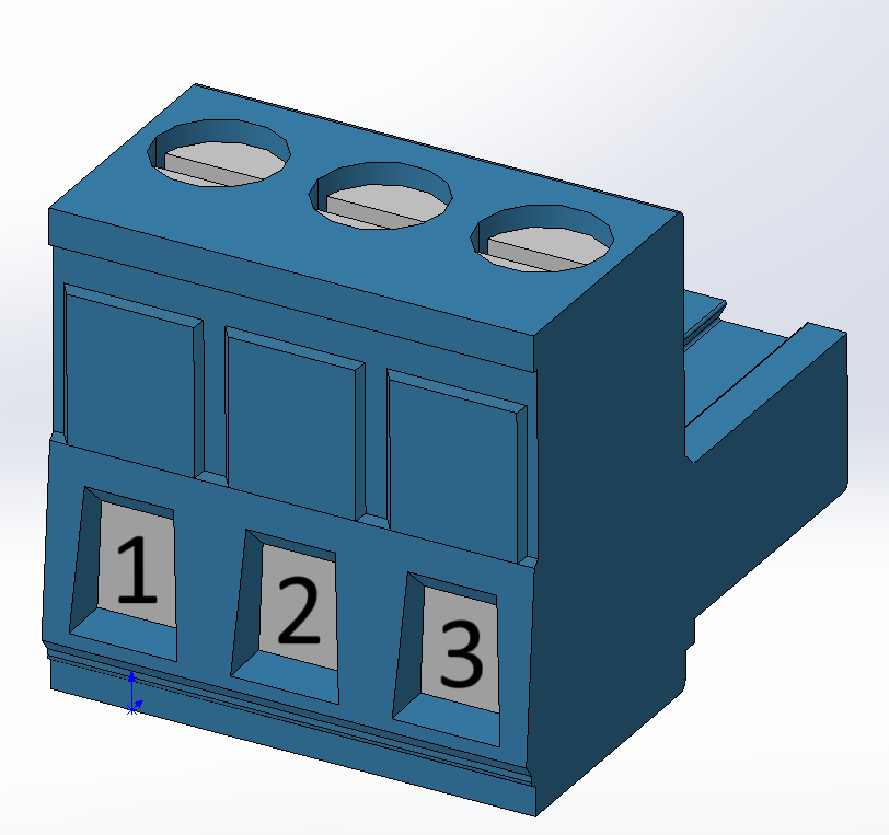
The 3-pin interface uses a Same Sky terminal-block plug, P/N TBP01P1-508-03BE, or equivalent. Its screw-cage clamps accept the transducer wires directly.
| Part Number | Manufacturer | Description |
|---|---|---|
TBP01P1-508-03BE | Same Sky | 3-position terminal-block plug, 5.08 mm pitch |
6-Pin Interface — Mid-2025 and Earlier
| Pin Number | I/O | Pin Name | Notes |
|---|---|---|---|
1 | O | TR_OUT | TR node |
2 | O | TRANSDUCER_OUT_P | Transducer output |
3 | O | AMP_OUT | Internal amplifier node |
4 | P/I | GND/TRANSDUCER2 | Board ground or second transducer input |
5 | O | AMP_OUT | Internal amplifier node |
6 | P | GND | Board ground |
- Connect the transducer between pins
2and6. - Pins
1and3are normally shorted with a jumper. A series matching element may instead be inserted between them; contact Popoto Modem for details. - A parallel matching element may be inserted between pins
5and4; contact Popoto Modem for details. - For a second receive-only transducer, contact info@popotomodem.com. By default, pin
4is identical to pin6and connected to board ground.
Hardware Components
The 6-pin interface uses a Molex Mini-Fit Jr. connector, P/N 0039013065, or equivalent. The recommended contacts are Molex P/N 0039000074, suitable for 18–24 AWG wire. They can be crimped with Molex hand tool 0638190901; pre-crimped leads may also be used.
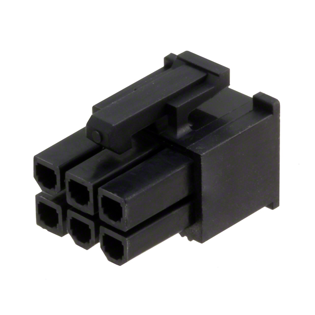
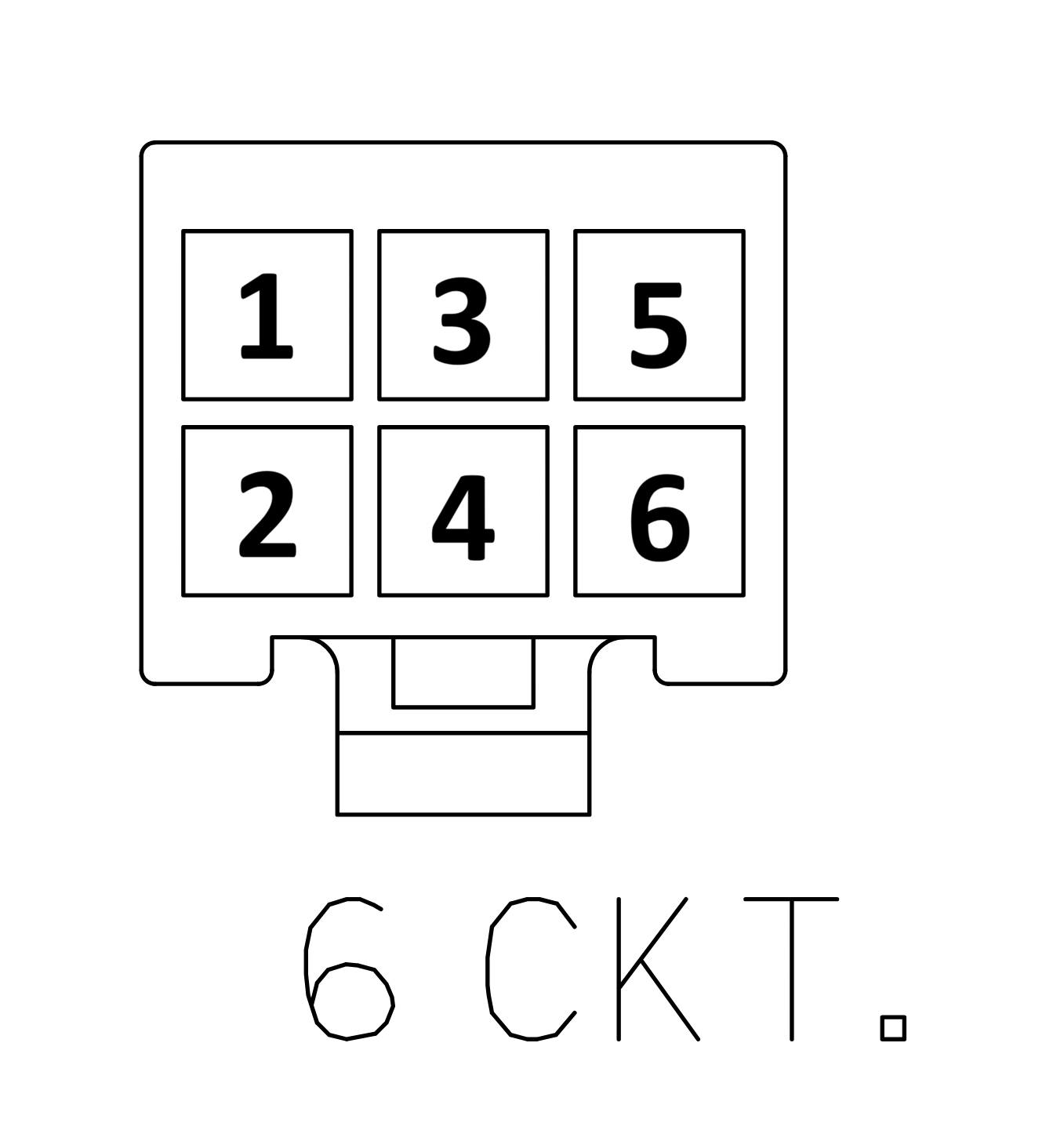
The pinout above matches the analog-board pinout but does not match the orientation shown in Molex drawing 0039013065.
| Part Number | Manufacturer | Description |
|---|---|---|
0039013065 | Molex | Mini-Fit Jr. 6-position connector receptacle, 4.2 mm pitch |
0039000074 | Molex | Mini-Fit Jr. 18–24 AWG gold-plated sockets |
0638190901 | Molex | Mini-Fit Jr. hand crimp tool |
2153431215 | Molex | Pre-crimped Mini-Fit Jr. lead, 450 mm length |
Mating Cable Notes
The Transducer Interface carries high voltage during modem transmissions. Voltages of hundreds to thousands of volts peak-to-peak can be present. Maintain proper clearance between exposed metal on this interface and all other metal.
Attach or detach the interface only while power is disconnected from the OEM modem to avoid electrical damage.