Analog Board Expansion Interface
Overview
The Analog Board Expansion Interface communicates with the modem MPU using +3.3 V logic-level digital peripherals. All pins are level-translated from the internal logic voltage to +3.3 V for robustness.
Electrical Connections
All signal directions are relative to the OEM modem. Refer to the analog board connector locations figure for the connector's physical location.
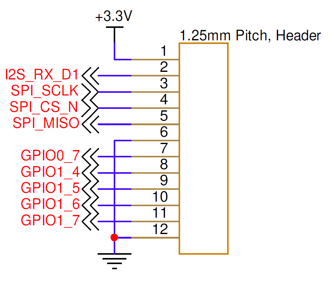
| Pin Number | I/O | Pin Name | Notes |
|---|---|---|---|
1 | P | +3.3V | +3.3 V out when unit is powered up |
2 | I | I2S_RX_D1 | I2S receive data pin |
3 | O | SPI_SCLK | SPI serial clock |
4 | O | SPI_CS_N | SPI slave select |
5 | I | SPI_MISO | SPI Master In Slave Out |
6 | P | GND | Board ground |
7 | I/O | GPIO0_7 | General-purpose I/O |
8 | I/O | GPIO1_4 | General-purpose I/O |
9 | I/O | GPIO1_5 | General-purpose I/O |
10 | I/O | GPIO1_6 | General-purpose I/O |
11 | I/O | GPIO1_7 | General-purpose I/O |
12 | P | GND | Board ground |
Application support
Contact info@popotomodem.com if your application requires the Analog Board Expansion Interface.
Hardware Components
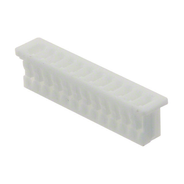
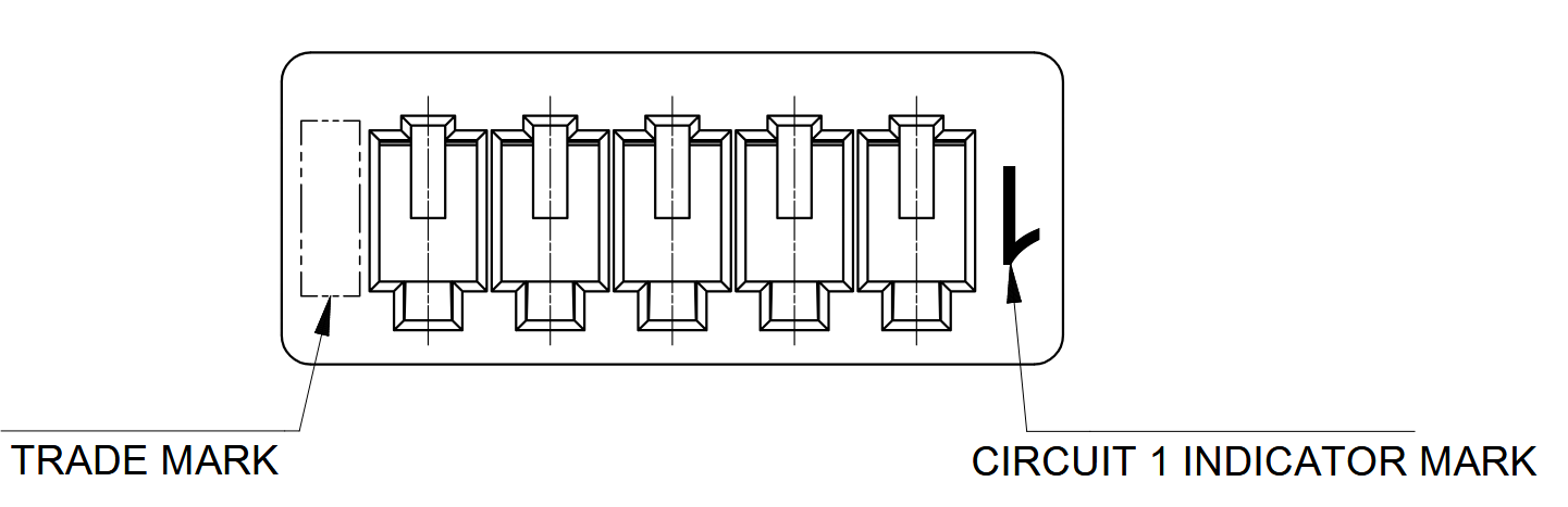
The Analog Board Expansion Interface uses a Molex PicoBlade connector, P/N 0510211200, or equivalent. The recommended contacts are Molex P/N 0500798000, suitable for 26–28 AWG wire.
| Part Number | Manufacturer | Description |
|---|---|---|
0510211200 | Molex | PicoBlade 12-position connector receptacle, 1.25 mm pitch |
0500798000 | Molex | PicoBlade 26–28 AWG sockets |
2002181900 | Molex | PicoBlade hand crimp tool |
2149202211 | Molex | Pre-crimped PicoBlade lead, 75 mm length |
Mating Cable Notes
Attach or detach the interface only while power is disconnected from the OEM modem to avoid electrical damage.