Transducer Electrical Connections
The Transducer Interface is a single connector for attaching the acoustic communications transducer. Refer to the top connector locations figure for its physical location.
PMM4511 Transducer Schematic
The following figure shows the electrical schematic for the PMM4511 transducer interface.
All signal directions are relative to the OEM modem.
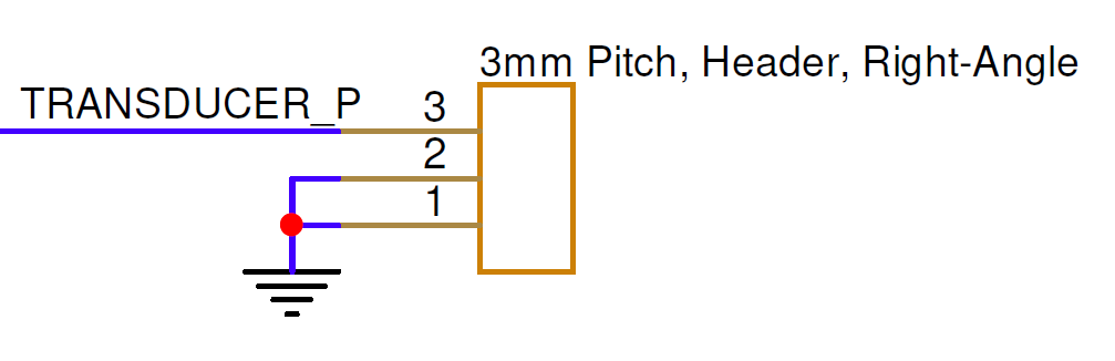
Transducer Interface Electrical Pinout
| Pin Number | I/O | Pin Name | Notes |
|---|---|---|---|
1 | O | TRANSDUCER_OUT_P | Transducer output |
2 | P | GND | Board ground |
3 | P | GND | Board ground |
Transducer wiring
Connect the transducer between pins 1 and 3, with the shield, if present, connected to pin 2.