Communication Interfaces
RS-422 Interface
Overview
The RS-422 Interface is a single connector providing the two differential pairs required for full-duplex RS-422 communication with the OEM modem.
Electrical Connections
All signal directions are relative to the OEM modem. Refer to the top connector locations figure for the physical location of the connector.
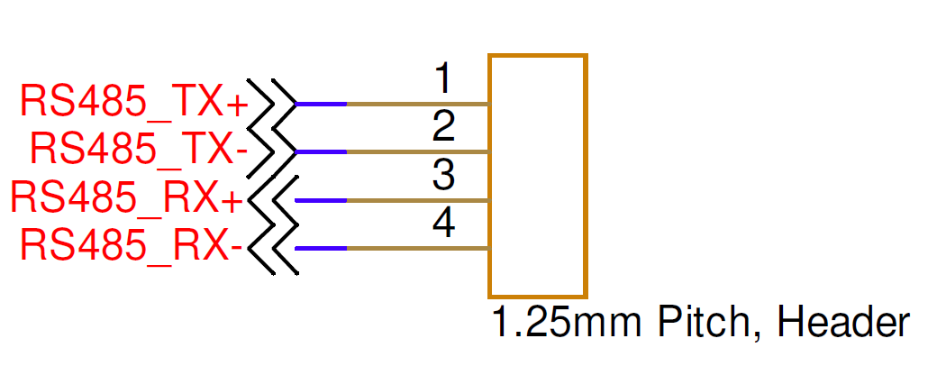
| Pin Number | I/O | Pin Name | Notes |
|---|---|---|---|
1 | O | RS-422 TX+ | RS-422 transmit positive |
2 | O | RS-422 TX- | RS-422 transmit negative |
3 | I | RS-422 RX+ | RS-422 receive positive |
4 | I | RS-422 RX- | RS-422 receive negative |
Hardware Components
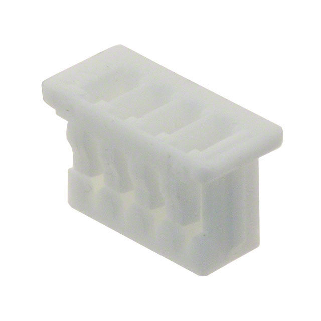
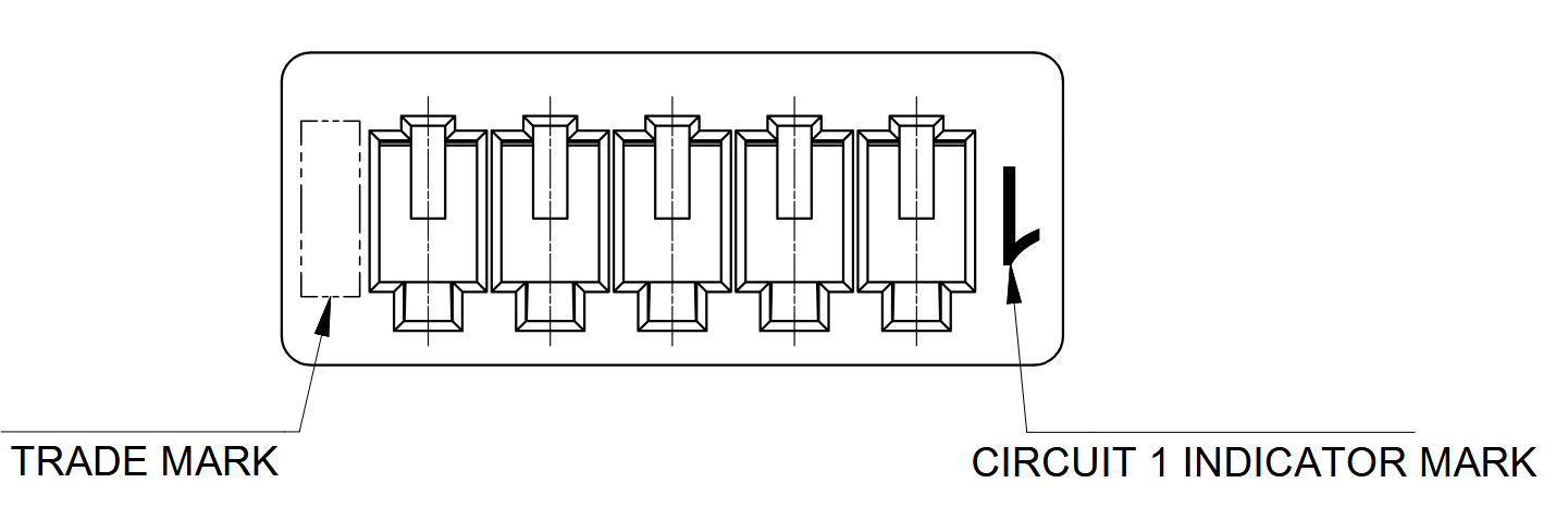
The RS-422 Interface uses a Molex PicoBlade connector, P/N 0510210400, or equivalent. The recommended contacts are Molex P/N 0500798000, suitable for 26–28 AWG wire. They can be crimped with Molex hand tool 2002181900, or pre-crimped wires may be used.
| Part Number | Manufacturer | Description |
|---|---|---|
0510210400 | Molex | PicoBlade 4-position connector receptacle, 1.25 mm pitch |
0500798000 | Molex | PicoBlade 26–28 AWG sockets |
2002181900 | Molex | PicoBlade hand crimp tool |
2149202211 | Molex | Pre-crimped PicoBlade lead, 75 mm length |
Mating Cable Notes
- Mating cables must use twisted-pair wiring for pins
1/2and3/4. - Attach or detach the interface only while power is disconnected from the OEM modem.
RS-232 Interface
Overview
The RS-232 Interface is a single connector providing the two signals required for full-duplex RS-232 communication with the OEM modem.
Electrical Connections
All signal directions are relative to the OEM modem. Refer to the top connector locations figure for the physical location of the connector.
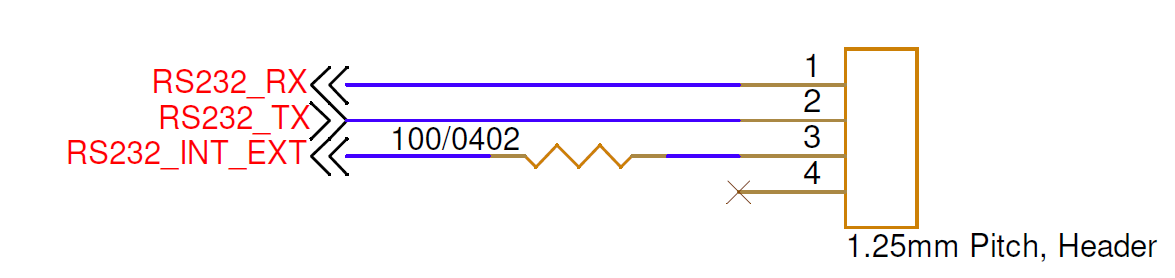
| Pin Number | I/O | Pin Name | Notes |
|---|---|---|---|
1 | I | RS-232 RX | RS-232 receive |
2 | O | RS-232 TX | RS-232 transmit |
3 | I | RS232_INT_EXT | General-purpose digital input or 1PPS; +1.8 V to +5 V logic level |
4 | - | NC | No connection on modem |
Hardware Components
The RS-232 Interface uses the same Molex PicoBlade connector components as the RS-422 Interface.
| Part Number | Manufacturer | Description |
|---|---|---|
0510210400 | Molex | PicoBlade 4-position connector receptacle, 1.25 mm pitch |
0500798000 | Molex | PicoBlade 26–28 AWG sockets |
2002181900 | Molex | PicoBlade hand crimp tool |
2149202211 | Molex | Pre-crimped PicoBlade lead, 75 mm length |
Mating Cable Notes
Attach or detach the interface only while power is disconnected from the OEM modem.
Ethernet Interface
Overview
The Ethernet Interface is a single connector providing the two differential pairs required for 10/100 Mbps Ethernet communication with the OEM modem.
Electrical Connections
All signal directions are relative to the OEM modem. Refer to the top connector locations figure for the physical location of the connector.
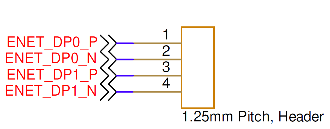
| Pin Number | I/O | Pin Name | Notes |
|---|---|---|---|
1 | O | ENET_DP0_P | T568A: green/white T568B: orange/white |
2 | O | ENET_DP0_N | T568A: green T568B: orange |
3 | I | ENET_DP1_P | T568A: orange/white T568B: green/white |
4 | I | ENET_DP1_N | T568A: orange T568B: green |
Hardware Components
The Ethernet Interface uses the same Molex PicoBlade connector components as the RS-422 Interface.
| Part Number | Manufacturer | Description |
|---|---|---|
0510210400 | Molex | PicoBlade 4-position connector receptacle, 1.25 mm pitch |
0500798000 | Molex | PicoBlade 26–28 AWG sockets |
2002181900 | Molex | PicoBlade hand crimp tool |
2149202211 | Molex | Pre-crimped PicoBlade lead, 75 mm length |
Mating Cable Notes
- Ethernet mating cables must use twisted-pair wiring, ideally with 100-ohm differential impedance, for pins
1/2and3/4. - Attach or detach the interface only while power is disconnected from the OEM modem.
TTL UART Interface
Overview
The TTL UART Interface is a single connector for communicating with the modem MPU using +3.3 V logic-level UART. The default UART parameters are 115200 8N1.
Electrical Connections
All signal directions are relative to the OEM modem. Refer to the top connector locations figure for the physical location of the connector.
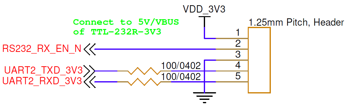
| Pin Number | I/O | Pin Name | Notes |
|---|---|---|---|
1 | P | VDD_3V3 | +3.3 V out when unit is powered up |
2 | I | RS232_RX_EN_N | Connect to pin 1, or to 3.3–5 V, to disable the RS-232 transceiver that shares this UART |
3 | P | GND | Board ground |
4 | O | UART2_TXD_3V3 | UART transmit, +3.3 V logic level |
5 | I | UART2_RXD_3V3 | UART receive, +3.3 V logic level |
Hardware Components
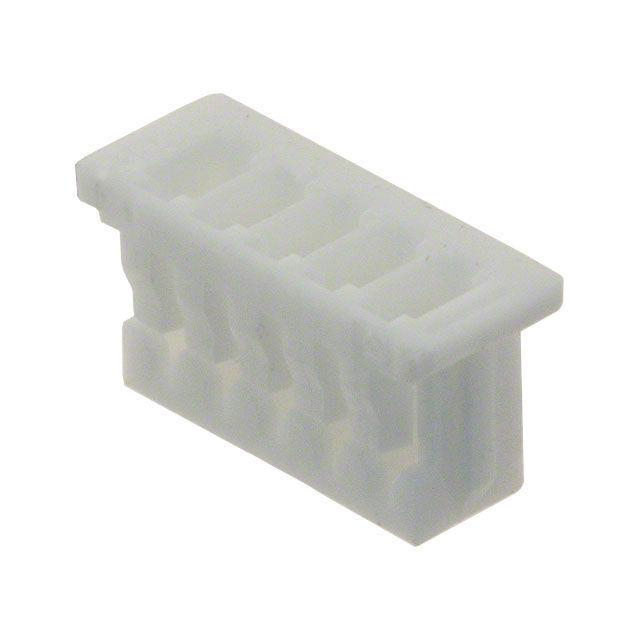
The TTL UART Interface uses a Molex PicoBlade connector, P/N 0510210500, or equivalent.
| Part Number | Manufacturer | Description |
|---|---|---|
0510210500 | Molex | PicoBlade 5-position connector receptacle, 1.25 mm pitch |
0500798000 | Molex | PicoBlade 26–28 AWG sockets |
2002181900 | Molex | PicoBlade hand crimp tool |
2149202211 | Molex | Pre-crimped PicoBlade lead, 75 mm length |
Mating Cable Notes
Attach or detach the interface only while power is disconnected from the OEM modem.
USB Interface
Overview
The USB port is a standard dual-role USB port configured by the Popoto Modem Linux operating system. It supports both host and peripheral connections. Contact info@popotomodem.com if your application requires the USB port.
OEM modem units manufactured before mid-2026 use a Micro-USB connector. Units revised around mid-2026 use a USB-C connector.