Transducer Interface
Overview
The Transducer Interface is a single connector for attaching the acoustic communications transducer. Refer to the top connector locations figure for its physical location.
Transducer Electrical Connections
All signal directions are relative to the OEM modem.
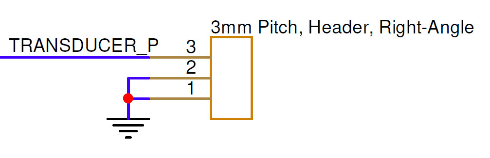
| Pin Number | I/O | Pin Name | Notes |
|---|---|---|---|
1 | O | TRANSDUCER_OUT_P | Transducer output |
2 | P | GND | Board ground |
3 | P | GND | Board ground |
Connect the transducer between pins 1 and 3, with the shield, if present, connected to pin 2.
Transducer Hardware Components
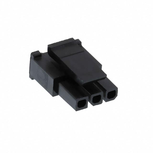
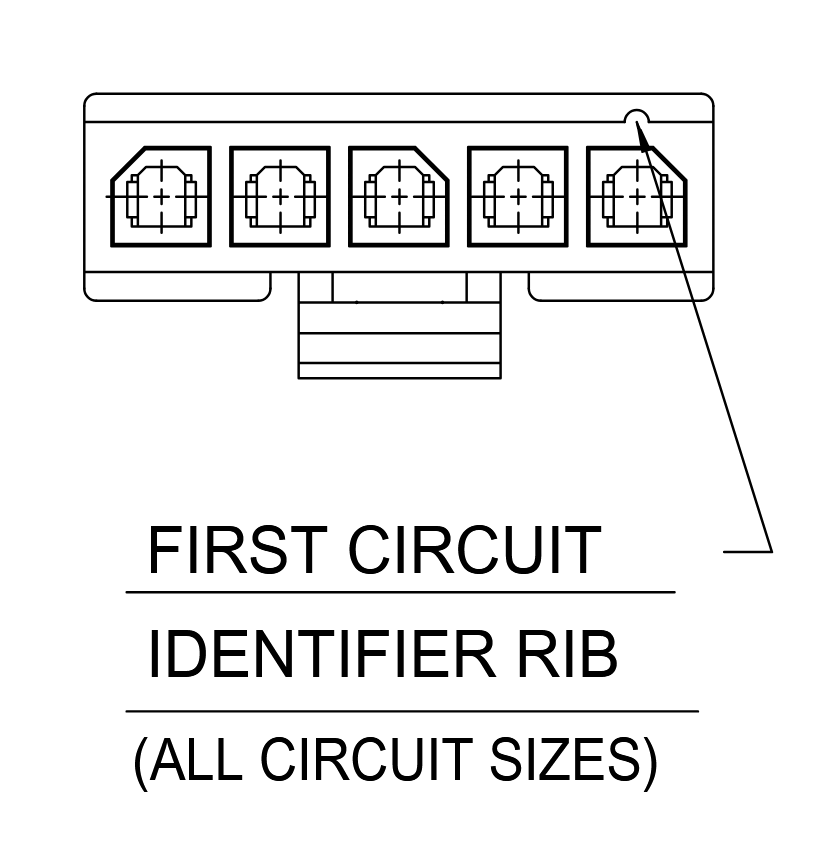
The Transducer Interface uses a Molex Micro-Fit 3.0 connector, P/N 0436450300, or equivalent. The recommended contacts are Molex P/N 0462355001, suitable for 20–24 AWG wire.
| Part Number | Manufacturer | Description |
|---|---|---|
0436450300 | Molex | Micro-Fit 3.0 3-position connector receptacle, 3.0 mm pitch |
0462355001 | Molex | Micro-Fit 3.0 20–24 AWG gold-plated, lubricated sockets |
0638190000 | Molex | Micro-Fit 3.0 hand crimp tool |
2147611215 | Molex | Pre-crimped Micro-Fit 3.0 lead, 450 mm length |
Mating Cable Notes
The Transducer Interface carries high voltage during modem transmissions. Voltages of hundreds to thousands of volts peak-to-peak can be present. Maintain proper clearance between exposed metal on this interface and all other metal.
Attach or detach the interface only while power is disconnected from the OEM modem to avoid electrical damage.