Power Interface
Overview
The Power Input Interface is a single connector that provides power to the board.
Electrical Connections
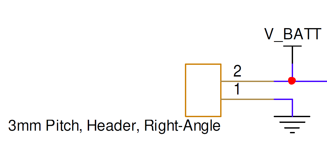
Pins labeled V_BATT, pin 2, and GND, pin 1, provide power to the OEM board.
- PMM4511-00: Allowable voltage range is 14–40 V, with a nominal expected voltage of 24 V.
- PMM4511WV-00: Allowable voltage range is 8.5–40 V, with a nominal expected voltage of 24 V.
Refer to the bottom connector locations figure for the physical location of the interface connector.
| Pin Number | I/O | Pin Name | Notes |
|---|---|---|---|
1 | P | GND | Board ground |
2 | P | V_BATT | PMM4511-00: 14–40 V, nominal 24 V; PMM4511WV-00: 8.5–40 V, nominal 24 V |
Hardware Components
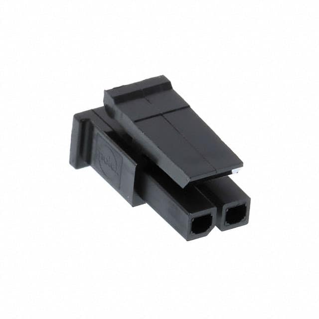
The Power Input Interface uses a Molex Micro-Fit 3.0 connector, P/N 0436450200, or equivalent. The recommended contacts are Molex P/N 0462355001. These gold-plated, low-insertion-force contacts are rated for 250 mating cycles and are suitable for 20–24 AWG wire.
The contacts can be crimped with a Molex hand tool such as 0638190000. Pre-crimped wires are also available from suppliers such as DigiKey.
| Part Number | Manufacturer | Description |
|---|---|---|
0436450200 | Molex | Micro-Fit 3.0 2-position connector receptacle, 3.0 mm pitch |
0462355001 | Molex | Micro-Fit 3.0 20–24 AWG gold-plated, lubricated sockets |
0638190000 | Molex | Micro-Fit 3.0 hand crimp tool |
2147611215 | Molex | Pre-crimped Micro-Fit 3.0 lead, 450 mm length |
Mating Cable Notes
- 20 AWG wire is preferred to reduce power losses during modem operation.
- Attach or detach the interface only while power is disconnected from the OEM modem to avoid electrical damage.