Ethernet Interface
Overview
The Ethernet Interface is a single connector providing the two differential pairs required for 10/100 Mbps Ethernet communication with the OEM modem.
Electrical Connections
All signal directions are relative to the OEM modem. Refer to the top connector locations figure for the physical location of the connector.
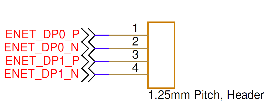
| Pin Number | I/O | Pin Name | Notes |
|---|---|---|---|
1 | O | ENET_DP0_P | T568A: green/white T568B: orange/white |
2 | O | ENET_DP0_N | T568A: green T568B: orange |
3 | I | ENET_DP1_P | T568A: orange/white T568B: green/white |
4 | I | ENET_DP1_N | T568A: orange T568B: green |
Hardware Components
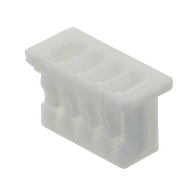
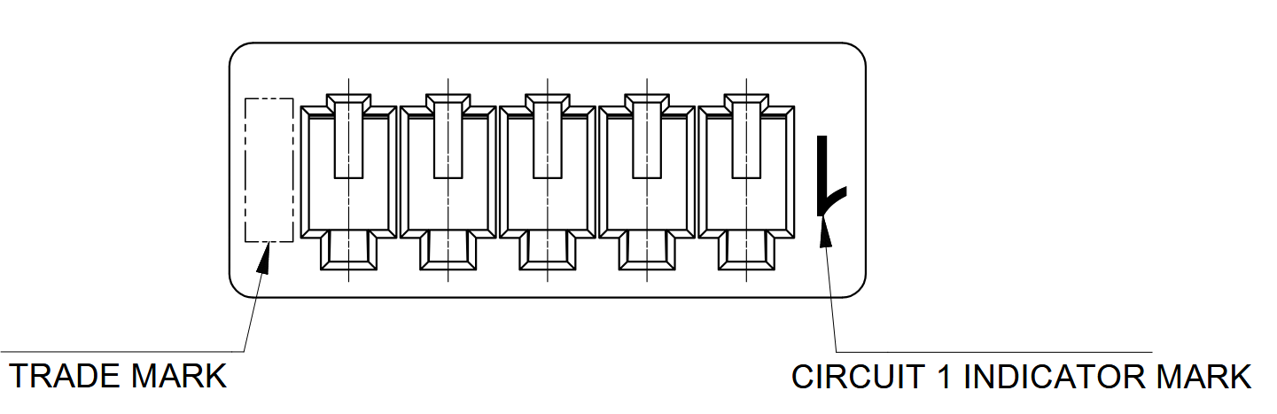
The Ethernet Interface uses the same Molex PicoBlade connector components as the RS-422 Interface.
| Part Number | Manufacturer | Description |
|---|---|---|
0510210400 | Molex | PicoBlade 4-position connector receptacle, 1.25 mm pitch |
0500798000 | Molex | PicoBlade 26–28 AWG sockets |
2002181900 | Molex | PicoBlade hand crimp tool |
2149202211 | Molex | Pre-crimped PicoBlade lead, 75 mm length |
Mating Cable Notes
- Ethernet mating cables must use twisted-pair wiring, ideally with 100-ohm differential impedance, for pins
1/2and3/4. - Attach or detach the interface only while power is disconnected from the OEM modem.