TTL UART Interface
Overview
The TTL UART Interface is a single connector for communicating with the modem MPU using +3.3 V logic-level UART. The default UART parameters are 115200 8N1.
Electrical Connections
All signal directions are relative to the OEM modem. Refer to the top connector locations figure for the physical location of the connector.
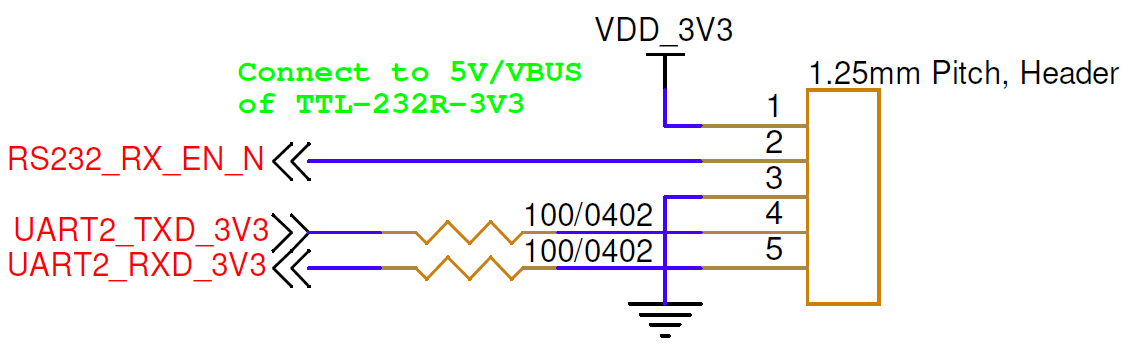
| Pin Number | I/O | Pin Name | Notes |
|---|---|---|---|
1 | P | VDD_3V3 | +3.3 V out when unit is powered up |
2 | I | RS232_RX_EN_N | Connect to pin 1, or to 3.3–5 V, to disable the RS-232 transceiver that shares this UART |
3 | P | GND | Board ground |
4 | O | UART2_TXD_3V3 | UART transmit, +3.3 V logic level |
5 | I | UART2_RXD_3V3 | UART receive, +3.3 V logic level |
Hardware Components
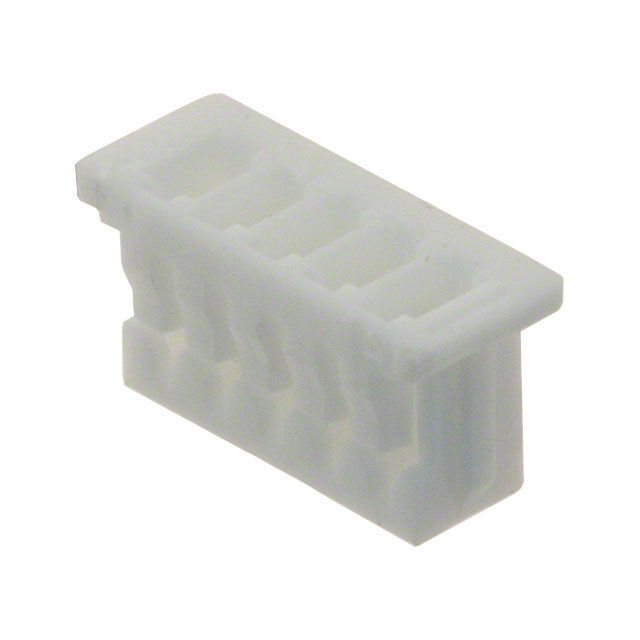
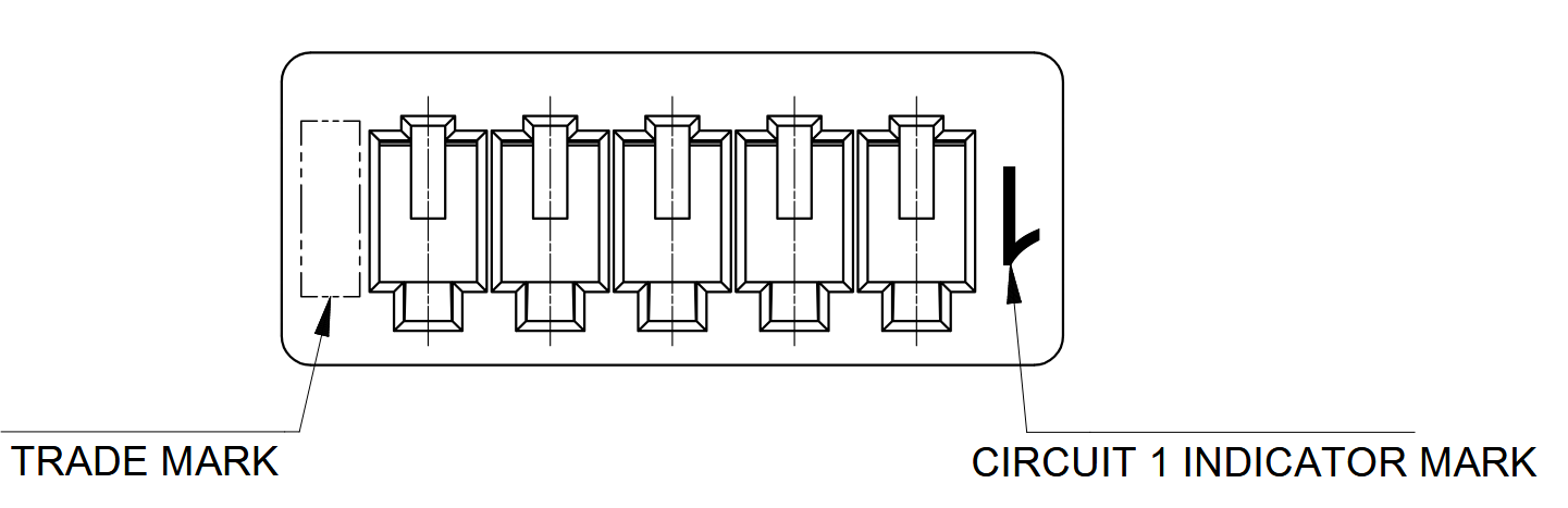
The TTL UART Interface uses a Molex PicoBlade connector, P/N 0510210500, or equivalent.
| Part Number | Manufacturer | Description |
|---|---|---|
0510210500 | Molex | PicoBlade 5-position connector receptacle, 1.25 mm pitch |
0500798000 | Molex | PicoBlade 26–28 AWG sockets |
2002181900 | Molex | PicoBlade hand crimp tool |
2149202211 | Molex | Pre-crimped PicoBlade lead, 75 mm length |
Mating Cable Notes
Attach or detach the interface only while power is disconnected from the OEM modem.