Analog Line Input Interface
Overview
The Analog Line Input Interface accepts an analog signal into the receiver pathway. The transducer receiver is normally digitized at separate 43 dB and 12 dB gains; using analog line input disconnects the transducer from the 12 dB pathway.
Move the Analog Input Selection Jumper from pins 1/2 to pins 2/3 before using this interface.
Electrical Connections
The interface is single-ended and AC-coupled through a 10 µF capacitor with a 10 kΩ input resistor, producing a 1.59 Hz high-pass cutoff and approximately 10 kΩ pass-band input impedance. Gain is −1 V/V with an intentional 123 kHz low-pass roll-off. The full-scale ADC input is 5.32 V peak-to-peak.
Refer to the analog board connector locations figure for the connector's physical location.
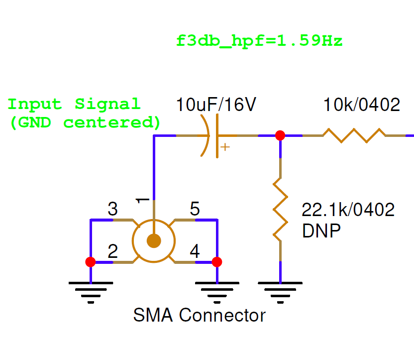
| Pin Number | I/O | Pin Name | Notes |
|---|---|---|---|
1, SMA center | I | LINE_IN | Analog line input |
2–5, SMA shell | P | GND | Board ground |
Hardware Components
The Analog Line Input Interface accepts any standard SMA cable. One example is TE Connectivity P/N CSE-SGAM-305-SGAM.