3-Pin Interface (Mid-2025 and Later)
Connector revision
OEM modems manufactured mid-2025 and later use a 3-pin terminal-block connector. For the 6-pin version, refer to 6-Pin Interface (Mid-2025 and Earlier).
PMM5544 3-Pin Transducer Interface
All signal directions are relative to the OEM modem.
Refer to the analog board connector locations figure.
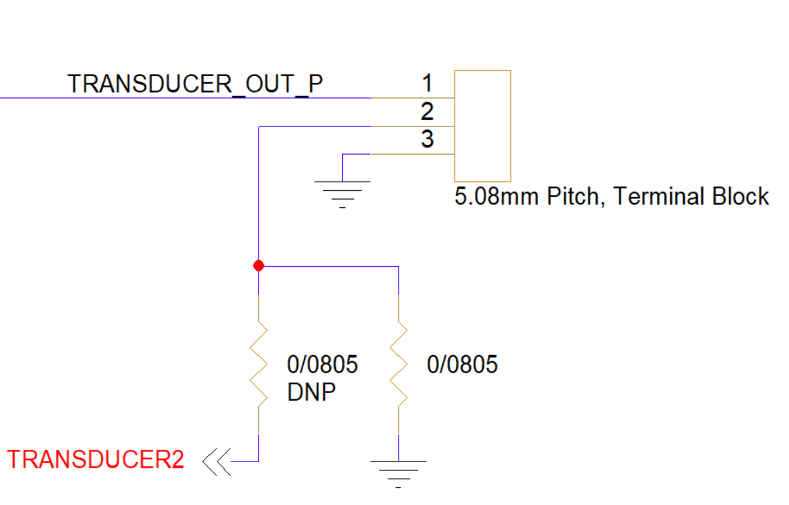
PMM5544 Electrical Pinout
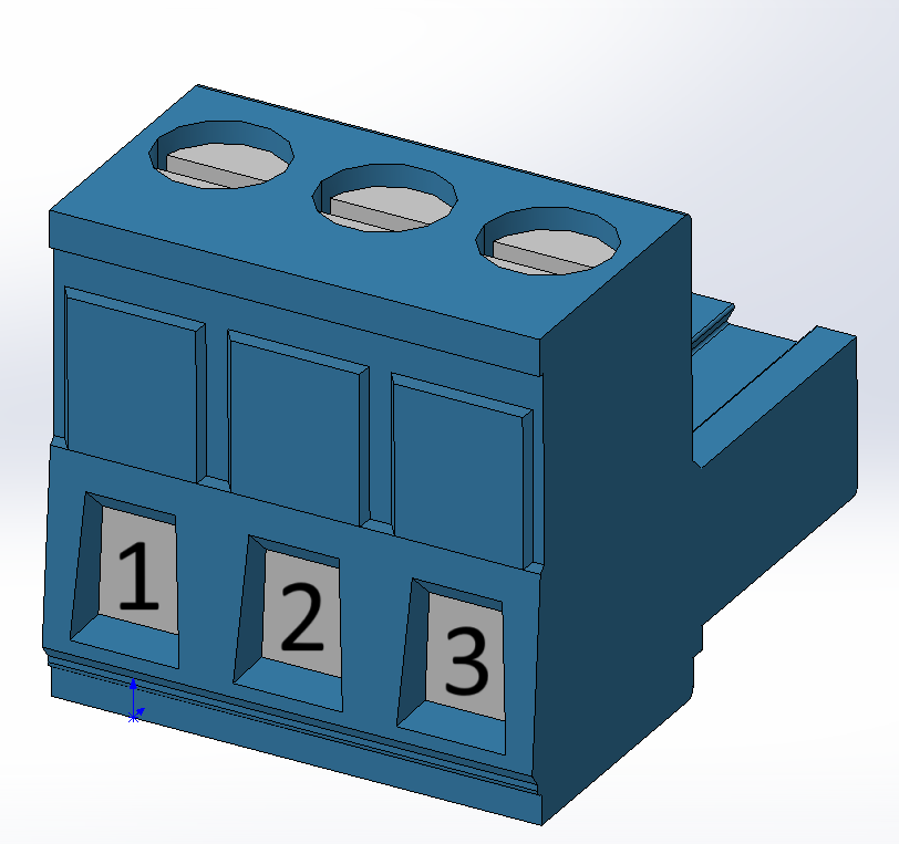
| Pin Number | I/O | Pin Name | Notes |
|---|---|---|---|
1 | O | TRANSDUCER_OUT_P | Transducer output |
2 | P/I | GND/TRANSDUCER2 | Board ground or second transducer input |
3 | P | GND | Board ground |
- Connect the transducer between pins
1and3, with the shield, if present, connected to pin2. - For a second receive-only transducer, contact info@popotomodem.com. By default, pin
2is identical to pin3and connected to board ground.
Hardware Components
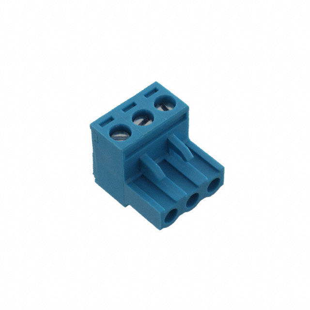
The 3-pin interface uses a Same Sky terminal-block plug, P/N TBP01P1-508-03BE, or equivalent. Its screw-cage clamps accept the transducer wires directly.
| Part Number | Manufacturer | Description |
|---|---|---|
TBP01P1-508-03BE | Same Sky | 3-position terminal-block plug, 5.08 mm pitch |