6-Pin Interface (Mid-2025 and Earlier)
Connector revision
OEM modems manufactured before mid-2025 use a 6-pin connector. For the 3-pin version, refer to 3-Pin Interface (Mid-2025 and Later).
note
The illustration in the analog board connector locations figure in the Interface Control Overview shows the 3-pin version.
PMM5544 Electrical Pinout
| Pin Number | I/O | Pin Name | Notes |
|---|---|---|---|
1 | O | TR_OUT | TR node |
2 | O | TRANSDUCER_OUT_P | Transducer output |
3 | O | AMP_OUT | Internal amplifier node |
4 | P/I | GND/TRANSDUCER2 | Board ground or second transducer input |
5 | O | AMP_OUT | Internal amplifier node |
6 | P | GND | Board ground |
- Connect the transducer between pins
2and6. - Pins
1and3are normally shorted with a jumper. A series matching element may instead be inserted between them; contact Popoto Modem for details. - A parallel matching element may be inserted between pins
5and4; contact Popoto Modem for details. - For a second receive-only transducer, contact info@popotomodem.com. By default, pin
4is identical to pin6and connected to board ground.
Hardware Components
The 6-pin interface uses a Molex Mini-Fit Jr. connector, P/N 0039013065, or equivalent. The recommended contacts are Molex P/N 0039000074, suitable for 18–24 AWG wire. They can be crimped with Molex hand tool 0638190901; pre-crimped leads may also be used.
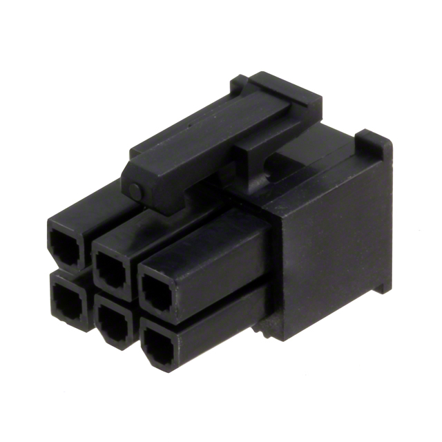
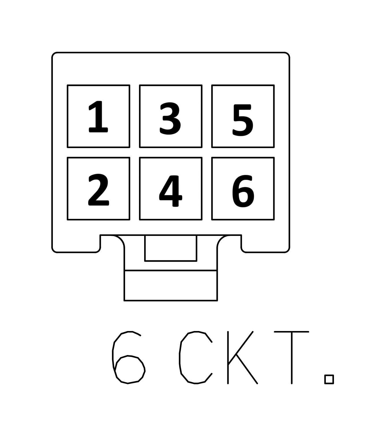
Pin-number orientation
The pinout above matches the analog-board pinout but does not match the orientation shown in Molex drawing 0039013065.
| Part Number | Manufacturer | Description |
|---|---|---|
0039013065 | Molex | Mini-Fit Jr. 6-position connector receptacle, 4.2 mm pitch |
0039000074 | Molex | Mini-Fit Jr. 18–24 AWG gold-plated sockets |
0638190901 | Molex | Mini-Fit Jr. hand crimp tool |
2153431215 | Molex | Pre-crimped Mini-Fit Jr. lead, 450 mm length |